|
Programmable
controller NLC-3
Description
|
|
 Programmable
logic controller (PLC) NLC-3 is a compact
controller dedicated for
realisation of control and regulation functions in various technology,
machines and for data acquisition. NLC-3 includes
processor,
EEPROM and RAM memory, real time clock, RS232 serial interface and maximum
two CAN interfaces. NLC-3 is powered from source 24V DC. The number and the
type of NLC inputs and outputs depends on selection of input and output
boards. Programmable
logic controller (PLC) NLC-3 is a compact
controller dedicated for
realisation of control and regulation functions in various technology,
machines and for data acquisition. NLC-3 includes
processor,
EEPROM and RAM memory, real time clock, RS232 serial interface and maximum
two CAN interfaces. NLC-3 is powered from source 24V DC. The number and the
type of NLC inputs and outputs depends on selection of input and output
boards.
Application software for NLC-3
controllers is developed in graphic
programming system HORSET. Horset was developed by our firm on the
base of French programming system GRAFCET, now probably better known as SFC
- Sequential Function Chart. The main difference between Grafcet a
Horset is the way of writing code. The graphic structure an the instructions
of program states are separated in Grafcet. The graphic structure and the
code instructions are written together in Horset and so the program is very
well readable and understandable even for peoples, that have practically no
experience with programming. Another special
property of Horset is the possibility of integration of many NLC-3
controllers, CIO modules and other products with CAN interface in one
project. NLC-3 knows automatically the state of all inputs and outputs and a
part of variables of other modules and their symbolic names can be used in
NLC program. Thanks to that it is very simple to build large-scale systems.
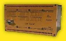
NLC-3 controllers are inbuilt in robust Dold enclosure
with 66 screw terminals for 35 mm DIN rail. |
|
|
Technical
data
|
Power source |
Power voltage
Power current |
24V±10% DC
max.250 mA |
| Technical
Resources |
Memory
Communication
Real Time Clock
back-up RAM
Watch-dog |
EPROM 64kB
EEPROM 32kB
RAM 128kB
1 channel RS232
2 channels CAN,
max.1Mbit/s
yes
yes, Li battery
100ms |
|
Binary Inputs |
| Number |
max. 24, 24V DC |
|
Analog Inputs |
Number
Range |
max. 16
±5V, ±10V, ±20mA |
|
Transistor Outputs |
| Number |
max. 24 , 24V 0.2A DC |
|
Relay Outputs |
| Number |
max. 24, 230V 5A |
|
Analog Outputs |
Number
Range |
max. 4
0-5V, 0-10V, ±5V, ±10V |
| Mechanical
Description |
Mounting
Dimensions
Mass |
for DIN rail 35mm
200 x 130 x 118 mm
900 g |
|
Working Conditions |
Temperature range
Protection |
0 ~ 50°C
IP 20 |
|
Connection |
Inpits/Outputs
CAN 1
CAN 2
RS232 |
66 screw terminals, wire cross-section
max. 2,5mm2 9 pin CANON
9 pin CANON |
Programming system HORSET
Horset
development was inspired by GRAFCET and SFC (Sequential Function Chart)
part of IEC1131-3 standard.
The program combines graphic
structure of control process with description of instructions executed at the
states and conditions determining transitions of control process from one state
to another.
Instructions executed
at the state are written immediately to the right and down from the state
graphic shape. The transition logic condition is written to the right and down
from the transition graphic shape. Any state can have many transitions to
different next states. The transition conditions are evaluated from the left to
the right till some of them is true. At this moment control process goes to the
state subsequent the active transition, executes instructions written at this
states and evaluates its conditions.
Horset allows to create
parallel processes. Any control process can create one or more next parallel
processes. Two or more control processes can join to one process. The control
process can be also killed by other process. The states of active parallel
processes are executed step by step. At one program control loop active state
instructions and its transition conditions of any active parallel process is
executed. The state instructions are executed only once. If no transition
condition of the state is true, only transition conditions of the state are
evaluated in the next loop. NLC-3 allows minimum one and maximum 16 active
parallel processes at one moment.
Inputs, outputs,
variables and fields symbolic names are defined at tables. Variables can be
defined as boolean, byte, integer and long type. Fields are of integer type. The
names of inputs, outputs and variables of other NLC systems connected by CAN and
included in project can be used like its own.
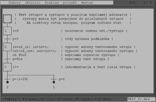
At this picture you can see a simple
program - the test of 24 NLC-3 inputs and outputs by using indirect
addressing. At the first state index variable i is zeroed. The
condition for transition to the next state is always true. At the state 2 at the
first line the address of tested input is calculated. The base address of
tested inputs is assigned to in variable at first and the the
index variable i is added. The address of switched on output is calculated at
the second line of state 2. The base address of tested outputs is assigned to
out variable at first and the the index variable i is added. The
output with calculated address is switched on by instruction on @out
at the third line.
The condition for transition from state 2 to state 3 is
true, when the input with indirect address @in is switched on.
Index variable i is incremented at the state 3. The state 3 has 2 alternative
conditions for transition to the next state. If index variable i is less then
24, program goes to state 2 and tests the next input. If i is equal 24, program
goes to state 1 and starts the new test cycle.
Horset programming system was
developed by programmers with wide experience of control systems implementation
in different types of technology. We developed and implemented at the end users
control systems of robots, monorail transport systems, weighing systems, data
acquisition systems, temperature regulation systems, etc.,etc. Thanks to that
Horset contains a lot of useful instructions that allows write application
software quickly, effectively and the software is well readable and
understandable.