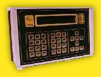
Operator terminal VTT-3
|
|
Terminal has 4x40 char display, 32 keys and 4 LEDs. It has two serial interfaces that can be selected as RS232, RS485, RS422 or LONworks. ISO 11898 CAN interface is the main communication port for high speed data exchange with other control components. VTT-3 can work as a passive terminal that displays data received on RS232 port and sends pressed key codes to serial link. At this mode no programming is needed. Serial link mode is selected at setup menu. At intelligent terminal mode the display data and key press meaning is given by application software. Software controls also data exchange on communication ports and VTT may be a main control unit solving automation or data acquisition tasks. MODBUS and UNIP protocols were implemented. Programming software allows implement any serial protocol in a short time. Implemented instructions allow directly control inputs and outputs of CAN linked CIO modules and exchange data with other CAN linked components. Terminal is produced at two mechanical construction versions. Front panel version is placed in Bopla CF310 front panel enclosure with foil membrane keypad and metallic backup cover. On wall mounting version is completely placed at plastic Bopla enclosure with IP54 protection. |
Power source | |
24V±25% max. 200 mA | |
Technical Resources | |
Memory Communication Real Time Clock Memory backup Watch-dog |
EPROM 64kB EEPROM 32 kB RAM 128 kB 1 channel CAN ISO11898 2 channel RS232, RS485,RS422 or LON yes yes, Li battery 100 ms |
Mechanical description | |
Front panel version Dimensions Mass On wall mounting version Dimensions Mass |
295 x 195 x 75 mm 800 g 295 x 260 x 125 mm 1000 g |
Working Conditions | |
Temperature range | 0 ~ 50°C |
Protection | |
Front panel Back side |
IP 54 IP 20 |
Pripojenie | |
RS232 RS485, RS422 CAN Power |
9 pin CANON female 9 pin CANON 4 pin screw terminals 4 pin screw terminals |
Application software is written in Basic like JPP programming language. Code is written in any text editor and then translated by JPP compiler. The result code is moved to terminal by RS232 interface.
JPP contains instructions for display control, key code and variable input, arithmetic and logical operations on variables, serial ports data transmission and receiving, CAN and LONworks data exchange, timing and instruction flow control operations.
Here is a simple program in JPP
clear; | { clear display } |
dispr 1," Hello, world "; | { text on 1st row } |
mode 96,n,8,0 | { set RS232 port mode } |
delay 200; | { pause 2 seconds } |
cycle: | { label } |
dispr 3," " | { clear 3rd row } |
disp "A=",3,5; input a:5; | { input A variable } |
disp "B=",3,25; input b:5; | { input B variable } |
c=a*b; | { multiple A and B } |
dispr 4," " | { clear 4th row } |
dispr 4," A=",a:5," B=",b:5," A * B = ",c:10; | { display variables multiplication } |
print " A=",a:5," B=",b:5," A * B = ",c:10; | { transmit variables text to RS232 } |
send 0dh; send 0ah; | { transmit CRLF to RS232 } |
goto cycle | { jump to cycle label } |
Program clears display, displays text in the 1st row, setup serial port mode and wait 2 seconds. Then in the 3rd row reads values for A and B variables, multiplies them and writes the result at the 4th row. The result is also sent as a text line to RS232 interface.
Variables are 32 bit long integer. Field variables should be defined explicitly, single variables may not. Subroutines can be used. Program can open 4 parallel threads. Thanks to that operator interface and communication tasks can be fully separated.